
International Journal of Scientific Engineering Research Volume 2, Issue 8, August-2011 1
Image Compression Using Discrete Cosine
Transform Discrete Wavelet Transform
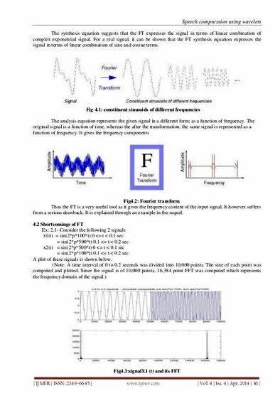
Abstract — Image compression plays a vital role in digital image processing. The need for image compression becomes apparent when number of bits per image are computed resulting from typical sampling rates and. quantization methods. For example, the amount of storage required for given images is (i) a low resolution, TV quality, color video image which has 512 x 512 pixels/color,8 bits/pixel, and 3 colors approximately consists of 6 x 10⁶ bits;(ii) a 24 x 36 mm negative photograph scanned at 12 x 10⁻⁶mm:3000 x 2000 pixels/color, 8 bits/pixel, and 3 colors nearly contains 144 x 10⁶ bits; (3) a 14 x 17 inch radiograph scanned at 70 x 10⁻⁶mm: 5000 x 6000 pixels, 12 bits/pixel nearly contains 360 x 10⁶ bits. Thus storage of even a few images could cause a problem.DCT is one of the transforms used for lossy image compression. This paper reveals a study of the mathematical equations of the DCT and its uses with image compression.
Index Terms— CR, DCT, IDCT, ISO, JPEG, TV
mage compression is very important for efficient transmission and storage of images. Demand for communication of multimedia data through the tele- communications network and accessing the multimedia data through Internet is growing explosively[14].With the use of digital cameras, requirements for storage, manipu- lation, and transfer of digital images, has grown explo- sively. These image files can be very large and can occu- py a lot of memory. A gray scale image that is 256 x 256 pixels has 65, 536 elements to store, and a a typical 640 x

480 color image has nearly a million. Downloading of these files from internet can be very time consuming task. Image data comprise of a significant portion of the mul- timedia data and they occupy the major portion of the communication bandwidth for multimedia communica- tion. Therefore development of efficient techniques for image compression has become quite necessary [9]. For- tunately, there are several methods of image compression available today. These fall into two general categories: lossless and lossy image compression. JPEG process is a widely used form of lossy image compession that centers around the Discrete Cosine Transform. The DCT works by separating images into parts of differing frequencies. During a step called quantization, where part of compres- sion actually occurs, the less important frequencies are discarded, hence the use of the term “lossy”. Then only the
most important frequencies that remain are used to re-
trieve the image in the decompression process. As a re-

Anitha S is currently pursuing PhD in Electonics and Instrumentation in
Dr.MGR University, Chennai. E-mail:anithasd@yahoo.com My guide is Dr Rajgopal C
sult, reconstructed images contain some distortion, but these levels can be adjusted during the compression stage.
The following is a general overview of the JPEG process. Later, we will take the reader through a detailed tour of JPEG’s method so that a more comprehensive under- standing of the process may be acquired.
1.

The image is broken into 8*8 blocks of pixels.
2. Working from left to right, top to bottom, the
DCT is applied to each block.
3. Each block is compressed through quantization.
4. The array of compressed blocks that constitute
the image is stored in a drastically reduced
amount of space.
5. When desired, the image is reconstructed through decompression, a process that uses the
Inverse Discrete Cosine Transform(IDCT) The DCT Equation
The DCT ( 1) computes the i,jth entry of the DCT
of an image.
JPEG stands for the Joint Photographic Experts Group, a standards committee that had its origins within the Inter- national Standard Organization (ISO).JPEG provides a compression method that is capable of compressing con- tinuous-tone image data with a pixel depth of 6 to 24 bits with reasonable speed and efficiency.JPEG may be ad- justed to produce very small, compressed images that are of relatively poor quality in appearance but still suitable for many applications. Conversely, JPEG is capable of producing very high-quality compressed images that are still far smaller than the original uncompressed data.
International Journal of Scientific Engineering Research Volume 2, Issue 8, August-2011 2
JPEG is primarily a lossy method of compression.JPEG was designed specifically to discard information that the human eye cannot easily see. Slight changes in color are not perceived well by the human eye, while slight changes in intensity (light and dark) are. Therefore JPEG’s lossy encoding tends to be more frugal with the gray- scale part of an image and to be more frivolous with the color[21].DCT separates images into parts of different frequencies where less important frequencies are dis- carded through quantization and important frequencies are used to retrieve the image during decompression. Compared to other input dependent transforms, DCT has many advantages: (1) It has been implemented in single integrated circuit; (2) It has the ability to pack most in- formation in fewest coefficients; (3) It minimizes the block like appearance called blocking artifact that results when boundaries between sub-images become visible [11].
The forward 2D_DCT transformation is given by (1):
C(u,v)=D(u)D(v) f(x,y)cos[(2x+1)uπ/2N]cos[(2 y+1)vπ/2N] (1) where u,v=0,1,2,3,—N-1
The inverse 2D-DCT transformation is given by the fol-
lowing equation
f(x,y)= f(x,y) cos[(2x+1)uπ/2N]cos[(2y+1)vπ/2N] (2) where
D(u)=(1/N) ^1/2 for u=0
D(v)=2(/N)^1/2 for u=1,2,3…….,(N-1)
3.1 JPEG Process
Original image is divided into blocks of 8 x 8.
Pixel values of a black and white image range from 0-255 but DCT is designed to work on pixel values ranging from -128 to 127 .Therefore each block is modified to work in the range.
is used to calculate DCT matrix.
DCT is applied to each block by multiplying the modified block with DCT matrix on the left and transpose of DCT matrix on its right.
Each block is then compressed through quantiza-
tion.
Quantized matrix is then entropy encoded.
Compressed image is reconstructed through re- verse process.
Inverse DCT is used for decompression[11].
most of the compression takes place.DCT really does not compress the image because it is almost lossless. Quanti- zation makes use of the fact that higher frequency com- ponents are less important than low frequency compo- nents. It allows varying levels of image compression and quality through selection of specific quantization matric- es. Thus quality levels ranging from 1 to 100 can be se- lected, where 1 gives the poorest image quality and high- est compression, while 100 gives the best quality and lowest compression. As a result quality to compression ratio can be selected to meet different needs.JPEG com- mittee suggests matrix with quality level 50 as standard matrix. For obtaining quantization matrices with other quality levels, scalar multiplications of standard quantiza- tion matrix are used. Quantization is achieved by divid- ing transformed image matrix by the quantization matrix used. Values of the resultant matrix are then rounded off. In the resultant matrix coefficients situated near the upper left corner have lower frequencies .Human eye is more sensitive to lower frequencies .Higher frequencies are discarded. Lower frequencies are used to reconstruct the image[11].
3.3 Entropy Encoding
After quantization, most of the high frequency coeffi- cients are zeros. To exploit the number of zeros, a zig-zag scan of the matrix is used yielding to long string of zeros. Once a block has been converted to a spectrum and quan- tized, the JPEG compression algorithm then takes the re- sult and converts it into a one dimensional linear array, or vector of 64 values, performing a zig-zag scan .
3.4Huffman coding:
The basic idea in Huffman coding is to assign short co- dewords to those input blocks with high probabilities and long codewords to those with low probabilities. A Huff- man code is designed by merging together the two least probable characters, and repeating this process until there is only one character remaining. A code tree is thus gen- erated and the Huffman code is obtained from the labe- ling of the codetree.
3.2 Quantization:
Quantization is achieved by compressing a range of val- ues to a single quantum value. When the number of dis- crete symbols in a given stream is reduced, the stream becomes more compressible. A quantization matrix is used in combination with a DCT coefficient matrix to car- ry out transformation. Quantization is the step where
International Journal of Scientific Engineering Research Volume 2, Issue 8, August-2011 3
4.1 Subband coding:
A signal is passed through a series of filters to calculate DWT. Procedure starts by passing this signal sequence through a half band digital low pass filter with impulse response h(n).Filtering of a signal is numerically equal to convolution of the tile signal with impulse response of the filter.
x[n]*h[n]= x[k].h[n-k] (3)
3.5 Results and Discussions:
Results obtained after performing DCT of various or- ders on original images are shown. Fig(3.1) shows origi- nal lena image. Images obtained after applying 8 x 8 DCT are as shown in Fig(3.2) whereas Fig(3.4) shows image obtained for same original image after applying 4 x 4
DCT. Fig(3.6) to Fig(3.10) show compressed images for the original Lena image after taking various number of coefficients for quantization.As the number of coefficients increases quality of the image decreases whereas com- pression ratio continues to increase.Fig(3.11) shows that SNR value increases with number of coefficients
Wavelet Transform has become an important method for image compression. Wavelet based coding provides sub
stantial improvement in picture quality at high com- pression ratios mainly due to better energy compaction property of wavelet transforms. Wavelet transform parti- tions
a signal into a set of functions called wavelets. Wave- lets are obtained from a single prototype wavelet called mother wavelet by dilations and shifting. The wavelet
A half band low pass filter removes all frequencies that are above half of the highest frequency in the tile signal. Then the signal is passed through high pass filter.The two filters are related to each other as
h[L-1-n]=(-1)ⁿg(n)
Filters satisfying this condition are known as quadrature
mirror filters. After filtering half of the samples can be
eliminated since the signal now has the highest frequency as half of the original frequency. The signal can therefore be subsampled by 2,simply by discarding every other sample. This constitutes 1 level of decomposition and can mathematically be expressed as in (4) (5)
Y1[n]= x[k]h[2n-k] k (4) Y2[n]= x[k]g[2n+1-k] k (5)
where y1[n] and y2[n] are the outputs of low pass and high pass filters, respectively after subsampling by 2.
This decomposition halves the time resolution since only
half the number of sample now characterizes the whole
signal. Frequency resolution has doubled because each output has half the frequency band of the input. This process is called as sub band coding. It can be repeated further to increase the frequency resolution as shown by the filter bank.
International Journal of Scientific Engineering Research Volume 2, Issue 8, August-2011 4
4.6 DWT Results:
Results obtained below. Fig(4.3.1) shows original Lena image. Fig(4.3.2) to Fig(4.3.4) show compressed images for various threshold values. As threshold value increases blurring of image continues to increase.
4.2 Compression steps:
1. Digitize the source image into a signal s, which is a string of numbers.
2. Decompose the signal into a sequence of wavelet coef- ficients w.
3. Use threshold to modify the wavelet coefficients from
w to w’.
4. Use quantization to convert w’ to a sequence q.
5. Entropy encoding is applied to convert q into a se-
quence e.
4.3Digitization
The image is digitized first. The digitized image can be characterized by its intensity levels, or scales of gray which range from 0(black) to 255(white), and its resolu- tion, or how many pixels per square inch.
4.4Thresholding
In certain signals, many of the wavelet coefficients are close or equal to zero. Through threshold these coeffi- cients are modified so that the sequence of wavelet coeffi- cients contains long strings of zeros.
In hard threshold ,a threshold is selected. Any wavelet
whose absolute value falls below the tolerance is set to zero with the goal to introduce many zeros without losing a great amount of detail.
4.5Quantization
Quantization converts a sequence of floating numbers w’ to a sequence of integers q.The simplest form is to round to the nearest integer.Another method is to multiply each number in w’ by a constant k, and then round to the near- est integer.Quantization is called lossy because it intro- duces error into the process, since the conversion of w’ to q is not one to one function.
Entropy encoding
With this method ,a integer sequence q is changed into a
shorter sequence, with the numbers in e being 8 bit integ- ers The conversion is made by an entropy encoding table. Strings of zeros are coded by numbers 1 through 100,105 and 106,while the non-zero integers in q are coded by 101 through 104 and 107 through 254.
Comparisons of results for DCT and DWT based on vari- ous performance parameters :
Mean Squared Error (MSE) is defined as the square of
differences in the pixel values between the corresponding
pixels of the two images. Graph of Fig(4.4.1) shows that for DCT based image compression ,as the window size increases MSE increases proportionately whereas for DWT based image compression Fig(4.4.2) shows that MSE first decreases with increase in window size and then starts to increase slowly with finally attaining a con- stant value. Fig(4.4.3) and Fig(4.4.4) plot show required for compressing image with change in window size for DCT and DWT respectively. Fig(4.4.5) and Fig(4.4.6) indi- cate compression ratio with change in window size for DCT and DWT based image compression techniques re- spectively. Compression increases with increase in win- dow size for DCT and decreases with increase in window size for DWT.
International Journal of Scientific Engineering Research Volume 2, Issue 8, August-2011 5
In the thesis image compression techniques using DCT
and DWT were implemented.
DCT is used for transformation in JPEG standard. DCT performs efficiently at medium bit rates. Disadvantage with DCT is that only spatial correlation of the pixels in- side the single 2-D block is considered and the correlation from the pixels of the neighboring blocks is neglected. Blocks cannot be decorrelated at their boundaries using DCT. DWT is used as basis for transformation in JPEG
2000 standard. DWT provides high quality compression
at low bit rates. The use of larger DWT basis functions or wavelet filters produces blurring near edges in images. DWT performs better than DCT in the context that it avoids blocking artifacts which degrade reconstructed images. However DWT provides lower quality than JPEG at low compression rates.DWT requires longer compres- sion time.
R EFERENCES
[1] R. C. Gonzalez and R. E. Woods, “Digital Image
Processing”,Second edition,pp. 411-514, 2004.
[2] N. Ahmed, T. Natarajan, and K. R. Rao, Discrete cosine transform, IEEE Trans. on Computers, vol. C-23, pp. 90-93,1974.
[3] A. S. Lewis and G. Knowles, Image Compression Using the 2-D Wavelet Transform IEEE Trans. on Image Processing, Vol. I. NO. 2, PP. 244 – 250, APRIL 1992.
[4] Amir Averbuch, Danny Lazar, and Moshe Israeli,Image Compression Using Wavelet Transform and Multiresolution DecompositionIEEE Trans. on Image Processing, Vol. 5, No. 1, JANUARY 1996.
[5] M. Antonini. M. Barlaud and I. Daubechies, Image Coding using Wavelet Transform”,IEEE Trans. On Image Processing Vol.1, No.2, pp. 205 – 220, APRIL 1992.
International Journal of Scientific Engineering Research Volume 2, Issue 8, August-2011 6
[6] Robert M. Gray,IEEE, and David L. Neuhoff, IEEEQuantization, IEEE Trans. on Information Theory, Vol. 44, NO. 6,pp. 2325-2383, OCTOBER 1998.(invited paper).
[7] Ronald A. DeVore, Bjorn Jawerth, and Bradley J. Lucier,
Member,Image Compression Through Wavelet Transform Coding IEEE Trans. on Information Theory, Vol. 38. NO. 2, pp. 719-746, MARCH 1992.
[9] Greg Ames,Image Compression, Dec 07, 2002.
[10] S. Mallat, A Theory for Multiresolution Signal Decomposition: The Wavelet Representation, IEEE Trans. on Pattern Analysis and Machine Intelligence, Vol. 11, No.7, pp. 674-693, July 1989.
[11] ken cabeen and Peter Gent,Image Compression and the
Descrete Cosine TransformMath 45,College of the Redwoods.
[12.] J. Ziv and A. Lempel, “A Universal Algorithm for Sequential
Data Compression,” IEEE Trans. on Information Theory, Vol. 23, pp.
337–342, 1977. [13]srcsearchciomidmarket.techtarget.com/sDefinition/0,,sid18
[14] 3.interscience.wiley.com [15]en.wikipedia.org/wiki/Discrete_wavelet_transform. [16] vectorsite/ttdcmp 2.html.
3_gci212327,00.html. [18]encyclopedia.jrank.org/articles/pages/6760/Image- Compression-and-Coding.html [19]fileformat.info/mirror/egff/ch09_06.html
Previous answers to this question
This is a preview of an assignment submitted on our website by a student. If you need help with this question or any assignment help, click on the order button below and get started. We guarantee authentic, quality, 100% plagiarism free work or your money back.
 Get The Answer